Teaching Minds-On Experiments on Electromagnetism in Secondary Schools

One loop motor
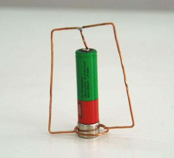
Elements of  the set:

  1. Neodymium magnet.
  2. Volta pile  R6 (1,5 V).
  3. Loop (1-2 mm diameter) from  Cu wire (1-2 mm dia.), see fig.
Electromagnetic engine in order to work requires:
- the source of magnetic field (neodymium magnet  - 1),
- electric current flowing in engine windings  (loop - 3), placed in this field

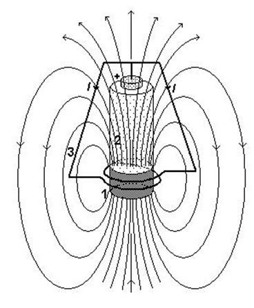
   Lay-out of the engine
Principle of operation of two-loop engine
Electromagnetic engines working is based on the principle of interaction between the magnetic field and the electric current. The permanent (and strong) neodymium magnet creates the magnetic field with a configuration shown on the fig. 1. In the region of the upper segment of the loop the field is almost vertical, and in the region of the lower segment it is directed in the opposite direction as compared to the upper part, and it is much weaker 5).
The electrical current flows from the „+” pole of the battery and the circuit is closed by the magnet (there is no isolation on the wire wound around the magnet). The gap between the wire loop and the magnet causes some discontinuity in the current flow but it does not disturb the engine operation too much.

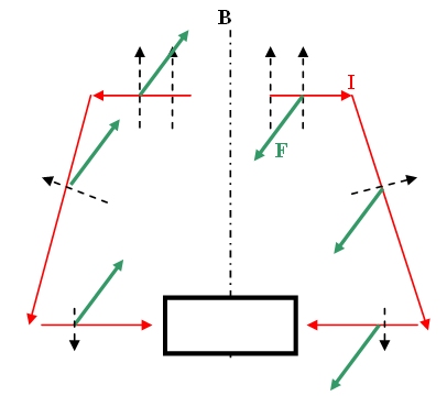
Moments of force acting on the loop
in the field of the magnet
The direction of the force acting on every part of the wire is defined by the right hand rule (thumb indicates the current, the indice – the magnetic field direction, the middle – the force). Alternatively, one can also use the vector product F=qv x B. It turns out that the particular geometry of the loop assures that the magnetic filed is approximately perpendicular to all three single segments, assuring therefore the maximum force. As seen from the fig. 2. the force moments acting on the two „wings” of the loop do sum up. The engine turns around!
 
In order to invert the direction of rotation one can invert the battery or the poles of the magnet.
Principles to learn:
- Lorentz’s force  acting on moving electrical charges (F = Bqv sinα , or  F=qv x B)
- electromagnetic force acting on the wire with electrical current (F = BIl sinα , or F=I  l x B)  ,
- right hand rule.
 
1) In paper: H. J. Schlichting i C. Kuce, Physik in unserer Zeit 35 (2004) 272, this engine is quoted as invented by Per-Olofa Nilssona from Sweden. 
2) I Liceum Ogólnokształcące w Toruniu
3) Antwerp University
4) Instytut Fizyki, UMK w Toruniu
5) The lower segment on the wire loop is positioned in the middle of the magnet, where the field is almost zero. The can be easily checked by using the magnetic field indicator (MOSEM experimental kit, part no 1.1)
[1] „Two-loop motor”, MOSEM Project, Low-tech kit, http://dydaktyka.fizyka.umk.pl/foton/silnik.wmv
[2] „Magnetic writer” http://dydaktyka.fizyka.umk.pl/zabawki/files/elmag/znikopis.html, in „Physics and Toys”, G. Karwasz, editor, PAP Słupsk (2005)